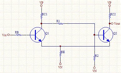
Combining these two stages into one involves nothing more complicated than replacing the npn transistors with pnp types. This solution uses just components. These oscillators are especially important because they are present in the internal oscillator in many popular MCUs. Any type of input voltage can be converted into its corresponding square signal wave.
Schmitt Trigger using Transistors. The only condition is that the input signal must have large enough excursion to carry the input voltage beyond the limits of the hysteresis range. Hence, it can be used as a level detecting circuit.
Instrumentation and Electrical Design. Another blog about transistors. Denna koppling genererar alltså en så kallad hysteres vilket är nyttigt när inkommande signaler är brusiga eller långsamma (annars kan det hända att operationsförstärkaren ändrar tillstånd flera gånger). Even if only a small amount of hysteresis is use it reduces the multiple transitions that can occur around the point of switching. The hysteresis makes inputs more immune to noise.
Ans: Greater than one. ON and QOFF or vice versa. To view the application note, click on the URL below. These devices are also useful for reshaping signals in complex layouts, and can prevent multiple switching when driven by slow edges. They feature a wide voltage supply range, input hysteresis, and CMOS and TTL variants.
If you have a noisy digital signal that requires cleaning, and redefining with sharp edges, then this circuit does the job well. In comparators, ideally the transition from one state to another state should be instant, but practically it will take certain time to switch from one state to another state. I thought for a schmitt trigger it generate two threshold values? It is by design. Imagine if your component values are such that the trip voltages are impossible to reach.

The output remains in one of the stable states indefinitely. The transition from one stable state to the other takes place when the input signal changes appropriately ( triggers appropriately). My application of interest required an astable design , shown in Figure 2. At the initial step, the threshold is set to the right value, depending on the inputs. At every subsequent crossing, the threshold is set to a new value, to take into account the hysteresis. This page describes basics of schmitt trigger.
Unfortunately there are hidden states. The approach is based on studying the transient from one stable state to another when the trigger is in linear operation. This method can minimize power consumption silicon and surface area.
In VLSI design , a great deal of effort has been made to explore low-power and area design options. The first step in the new design is splitting the output inverter of Figure 3. However, when the input voltage reaches 1. The cascade architecture used in this design limits lowering the operating voltage. I want to design a schmitt trigger using LM3with UTP=12V, LTO=10V This is the diagram given in LM3datasheet.
How will I set the Vref. Can someone give me the verified design with resistor values. The schmitt trigger part (Qand Q3) actually works. Check the possible voltages at Qcollector: When Qis off, it is obviously close to the supply voltage. Therefore, there will be current through Rand Qwill conduct.
LED flasher based on schmitt trigger version 2. This circuit is based on the schmitt trigger version 2. Qis a PNP that amplifies the output, it requires a low voltage of (Vcc – V or less) to turn on and a high voltage of near Vcc to turn off. These voltage levels are the requirement for this design to work.

Inga kommentarer:
Skicka en kommentar
Obs! Endast bloggmedlemmar kan kommentera.